| Home | Papers | Reports | Projects | Code Fragments | Dissertations | Presentations | Posters | Proposals | Lectures given | Course notes |
|
|
Real Time UMLWerner Van Belle1*+ - werner@yellowcouch.org, werner.van.belle@gmail.com Abstract : This document reports on task 2.1: an extensive literature study of existing modeling techniques for real time embedded systems. These include UML-RT, UML for Embedded Systems, Octopus, ROOM and others
Keywords:
component based development, seescoa, real-time embedded systems |
Table Of Contents
Introduction
Task 2.1: Real-time UML
Objectives: Get a firm hold on the state of the art. Investigate the applicability of existing modeling techniques (UML, …) specifically for embedded systems.
Methodology: Extensive literature study. Extensions of UML for modeling real-time aspects are currently under development (see section 2.2 state of the art). In the first place the state of the art of UML and its extensions and variations towards modeling real-time aspects will be investigated. Particular attention will be given to the issues involved in embedded systems design. Other methodologies will also be considered if they appear to be relevant from the results of WP 1 or in the course of the literature study itself.
Deliverable:
D 2.1 Assessment of applicability of existing modeling techniques
with possible suggestions for extensions and/or guidelines for using
existing features in particular ways.
The very nature of real-time embedded applications makes certain
characteristics of their implementation (such as timing and
implementation architecture) critical. Usually, the software in these
applications is responsible for the control of other equipment, so
designing a correct solution requires a systems view.
Most real-time embedded systems are, by nature, multitasking solutions to real-world problems. They typically deal with the interface and control of multiple external devices. The different parts of these systems usually run at different priorities and with different run-time characteristics. The notion of multiple tasks or threads being active in the system at the same time is common. Many of these real-time systems are deployed on a set of microprocessors in a distributed architecture. Designing a solution for this type of problem requires a system-level task design that captures these details.
UML-RT
The Unified Modeling Language (UML) provides a common framework for modeling object-oriented systems. In fact, UML's utility as a common language for defining and designing software systems independent of a specific implementation language has increased the acceptance of object-orientation in many software development areas.
UML is a third generation modelling language that rigorously defines the semantics of the object metamodel and provides a notation for capturing and communicating object structure and behavior. Many methodologists -- including Grady Booch (Booch Method), Jim Rumbaugh (Object Modeling Technique), Ivar Jacobson (Object-Oriented Software Engineering), and David Harel (Statecharts) -- collaborated to achieve UML. [1, 2, 3, 4, 5]
The Unified Modelling Language (UML)
UML combines graphical and textual notations to describe systems such as this. UML is primarily a set of notations and does not prescribe a specific development process.
Requirements Analysis:
One of the early activities in developing any system is to ensure that you understand the requested requirements, such as basic system functionality, timing constraints, and specific hardware constraints. There are two primary UML representations used to define the system requirements:
-
Use Case Diagrams, which represent interactions between external "actors" (users or devices) and the functions of the system. These interactions combine to form functional capabilities of the system. Through Use Case Diagrams, you can establish a set of functional, testable uses of the system that satisfy the stated requirements. Each Use Case Diagram describes some important functional capability of the system that is further elaborated with one or more Sequence Diagrams.
-
Sequence Diagrams, which capture a specific scenario or processing thread through the application using a pseudocode description (left side of the Sequence Diagram). The mapping of the Use Case functionality onto object actions is captured in the message sequence structure (right side of the Sequence Diagram). It is the communication (or collaboration) between the objects that collectively implement this Use Case.
Designing the System
UML supports a number of views to represent the design architecture that specifies how the solution will be implemented. This is done primarily through two architectural views -- Class and Collaboration Diagrams.
Class Diagrams form the basis for the logical object architecture of the system. Objects identified in earlier analysis steps are organized into basic class relationships of:
-
Inheritance, which captures the levels of abstraction of the object architecture through a hierarchy of superclass and subclass relationships.
-
Aggregation, which provides the basic mechanism for composition. An object can be made up of other objects, allowing for convenient problem decomposition and structural composition with clearly defined boundaries.
-
Association, which provides another mechanism to define the connectivity between objects that need to communicate with each other or support some other aspect of the system requirements.
The Collaboration Diagram, on the other hand, defines a communication structure between the objects. By analyzing several Sequence Diagrams together as a whole and representing the overall connectivity of the objects involved in those scenarios, it is possible to visualize the object-communication paths of the proposed design. This lets you create a more complete view of the overall communication architecture as opposed to any one specific scenario.
UML for Embedded Systems
Currently UML is being extended by a number of different organizations. Currently, there is no standard for UML-RT and as such we can't give an overview of UML-RT. Nevertheless we have incorporated a set of views by different authors.
Real Time Extensions
The issues of real-time support in UML are being addressed by the RTAD (Real-Time Analysis and Design) working group of the Object Management Group (OMG). This working group has representatives from several tool vendors (including Artisan Software Tools, http:// www.artisansw.com/) and other industry representatives. The approach we present here is Artisan's proposal. Although there are no standards yet, this approach embodies some of the fundamental concepts from the current thinking of RTAD.
Real-time systems are, by definition, constrained by some aspect of time. The requirements driving the development of these systems often state specific timing considerations. It is critical to capture this timing information while modeling the system to specify a reasonable system design and to support system test.
The two main categories of timing information that can be modeled in an object-oriented system are:
-
Latency, which is the amount of time it takes for two objects to collaborate (that is, to communicate via messaging).
-
Duration, which is the amount of time required for an object to perform its processing once it has received a message.
Through a combination of latency and duration specifications, we identify general timing constraints for a set of operations.
Sequence Diagram Revisited
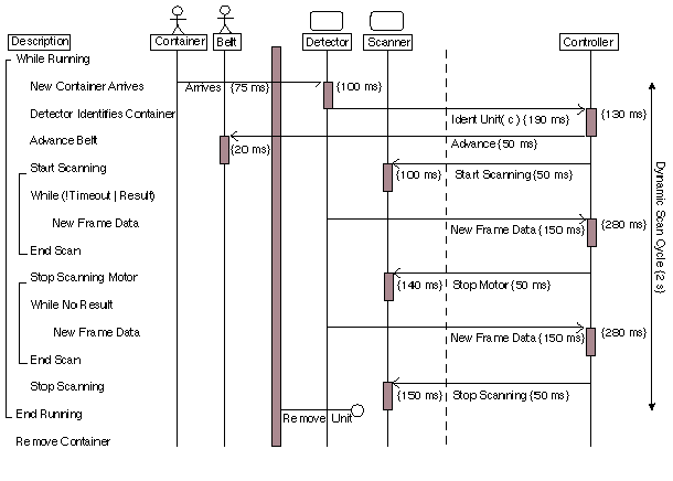
Sequence Diagrams provide a logical place in the modeling view to capture this timing information. The timing requirements associated with a particular system function are modeled in the Use Cases and mapped through the Sequence Diagram(s) onto specific interactions between objects. Where UML defines the notation and diagram contents, modern modeling tools supporting UML usually have some form of underlying repository for storing additional information and relationships. UML allows general notes to be added to any diagram. The definition of specific properties is not called out nor precluded by the UML definition. Modeling tools can support diagram annotation as well as diagram artifact attributes or properties. By making timing information an explicit attribute of the representations on the Sequence Diagram, the timing requirements are mapped directly onto the appropriate events and operations for each object and stored in the tool's repository. The timing information is then usable in other views of the system (class design). Artisan's Real-time Studio is one such tool that manages the timing information through explicit message properties.
|
The figure above illustrates specific timing attributes associated with the messages (horizontal lines) and the operations themselves (vertical blocks). For example, our process-control system has a 75 ms latency on the "Arrives" message that takes 100 ms to process the action. In addition to the individual timing attributes, it is also useful to specify overall timing constraints on a set of operations as on the far right side of the figure. Here, the total for the Dynamic Scan Cycle must be less than 2 seconds, thus making sure we can meet the 30 containers per minute requirement on the "Process Units" Use Case.
Something which is sometimes added to sequence diagrams for real time systems is initiation time, execution time, dwell time and deadlines.
-
Initiation time: initiation time is the time needed to prepare a process. Normally this is done only once
-
Execution time: execution time is the time needed to execute a given task. This task can be repeated several times without initiating again.
-
Dwell time: The dwell of a task is the time needed to round up a given execution. A deadline can be reached, but after the deadline some management (lets say garbage collection or something like that) has to be done. The time spend with cleaning up is called the dwell time.
-
Deadlines are marked as a horizontal bars upon the sequence diagram.
Timing Diagram
|
Another useful addition to UML is the use of timing diagram. Timing diagrams are not explicitly supported by the UML. Timing diagrams depict state as a horizontal band across the diagram. When the system is in that state, a line is drawn in that band for the duration of the time the system is in the state. The time axis is linear, although special notations are sometimes used to indicate long uninteresting periods of time. The simple form of a timing diagram is shown in the figure above.
Event handling
UML defines the message as the fundamental unit of object communication. This message captures the essential properties of the messages that are exchanged between the system and the actors interacting with it. Subsequent design will define the implementation of each message.
The arrival pattern of a message describes the timing behavior of the message group. UML does not describe these directly, but the definition of arrival patterns is crucial for analysis of schedulability and deadlines. Message arrivals can be episodic or periodic.
-
An episodic arrival pattern is inherently unpredictable, but it may still be bounded. Episodic messages may have a minimum interval time -- a minimum time that must occur between message arrivals. Episodic messages may also have an average rate -- a computed average frequency, even though the message arrivals may vary greatly from message to message. Episodic messages may be bursty, meaning that they tend to arrive in clumps. Episodic messages may be random, in which case the arrival of one message does not affect the probability of the arrival of the next (except for the minimum arrival time).
-
Periodic messages are characterized by a period with which the messages arrive, and by jitter, which is the variation around the period with which messages actually arrive. Jitter is normally modelled as a uniform random process but always totally within the jitter interval.
Synchronization patterns are explicitly, if somewhat weakly, supported by the UML standard. Synchronization defines the characteristics of the rendezvous of two objects that occurs during the exchange of a message. The synchronization patterns explicitly defined by UML are
-
Call: sender is blocked from continuing until the target completes its processing of the message. The call synchronization pattern models the yielding of control during a function or method call that occurs within a single thread of control.
-
Waiting: sender is blocked from continuing until the target completes its processing of the message. The waiting synchronization pattern models the yielding of control to another thread until the message processing is complete. Remote Procedure Calls (RPC's) are normally implemented using this synchronization pattern.
-
Asynchronous: The asynchronous synchronization pattern is inherently multi-threaded, because it models a message being passed to another object without the yielding of control.
Furthermore, Booch [1] also defines balking and timeout synchronization patterns, which are an extension to the core UML model.
-
Balking: The balking synchronization pattern models the behavior of one object aborting the message transfer if the other is not immediately available.
-
Timeout: The timeout synchronization pattern models the balking synchronization pattern except that a fixed waiting time is defined for the receiver object to accept the message.
Hardware Boundaries
There are three cases for the object-to-object communications in a multithreaded environment:
-
Within the same task (intratask).
-
Between two tasks on the same processor (intertask, intraprocessor).
-
Between two tasks on different processors (intertask, interprocessor).
In the latter two cases, the interaction should also be modeled in the system task design because the actual messaging will not be through direct object method calls. A tasking view of the system helps to understand the complex implementations of intertask messaging, shared data access, throughput, and synchronization issues. Representing the details of a multitasking view of the solution is difficult in the standard UML.
Concurrency Diagram
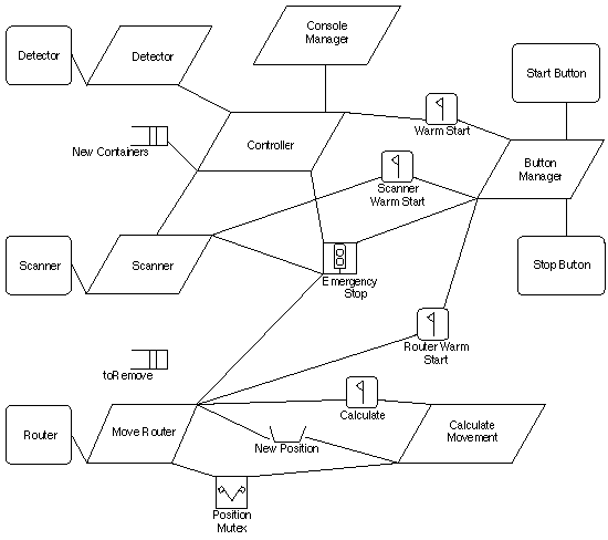
Artisan's approach for dealing with the multitasking design for a system using a Concurrency Diagram can be thought of as an extension of the Collaboration Diagram. The Concurrency Diagram shows several useful aspects of the system using additional notation for tasks and the intertask connections. By focusing this specialized view on the multitasking issues, we can model the overall task structure of the solution as well as the communication mechanisms between tasks. By dealing primarily with the active objects, it is possible to then map the object architecture into a multitasking solution. Nonactive objects can also be included in the Concurrency Diagram view for clarity of some interactions.
|
Concurrency diagram
Through the Collaboration Diagram(s), we tackle the definition of object interaction, which feeds into our task design. Another approach to task design is to model the natural concurrency in the problem domain.
UML has no straightforward provision for specifying the implementation of the interobject communications when they occur across task boundaries. The intertask communications are usually handled by the run-time environment either by constructing application-specific communication objects in the application (semaphores and queues) or by using primitives in the underlying executive. In either case, by modeling the communication mechanisms (queue, signal, and so on), the subsequent elaboration of these artifacts in the source code is better understood.
Hardware abstraction
Real-time embedded systems contain both hardware and software elements as part of the solution. A thorough understanding and representation of the physical structure, software/hardware interfaces, and system boundary is important for construction of an application that not only meets functional requirements but can be deployed into the proper environment.
|
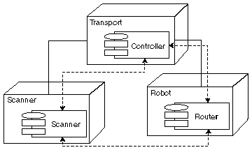
Deployment Diagram
UML provides a Deployment Diagram (see figure above) for capturing some of this information. The Deployment Diagram shows various nodes in our system with packages and processes (tasks) enclosed in these nodes and connections between the nodes and items on the nodes. However, in real-time embedded systems, the physical architecture has implications beyond simple placement of software on connected nodes. The types of connections (point-to-point, multidrop bus, or whatever) between the nodes, as well as the connectors (PCI, serial, ISDN, and so on) can play an important role in defining the proper architecture for the system. More importantly, the node characteristics themselves (processor configuration and memory maps) are vital to deployment and debugging of the target system.
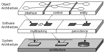
|
Conceptual view of the Solution Architecture layers and logical mappings of information between them.
To examine the software/hardware mapping more closely, Artisan defines three separate layers of the system called the "Solution Architecture." These layers are modeled as Object, Software, and System Architectures. The above figure shows a conceptual view of these three layers along with the logical mappings of information between them. This multilayer view will help us put the other views in perspective. One of the strengths of using a modeling tool for capturing the various views of the system is that it also allows you to relate information between the views. This capability is not readily available in simple drawing tools and not very extensive in some modeling tools.
Capsules, Ports & Connectors
When the semantics of a UML metaclass must be refined, a new UML stereotype is introduced. This section introduces the important Capsule, Port, and Connector, stereotypes that have been introduced into UML for Real-Time to support the modeling of complex real-time systems.
Capsules are complex, potentially concurrent, and possibly distributed active architectural components. They interact with their surroundings through one or more signal-based boundary objects called ports. Collaboration diagrams are used to describe the structural decomposition of a Capsule class.
A port is a physical part of the implementation of a capsule that mediates the interaction of the capsule with the outside world—it is an object that implements a specific interface. Ports realize protocols, which define the valid flow of information (signals) between connected ports of capsules. In a sense, a protocol captures the contractual obligations that exist between capsules. Because a protocol defines an abstract interface that is realized by a port, a protocol is highly reusable.
Ports provide a mechanism for a capsule to export multiple different interfaces; each tailored to a specific role. They also provide a mechanism to explicitly connect an exported interface of one capsule directly to the interface of another capsule. By forcing capsules to communicate solely through ports, it is possible to fully de-couple their internal implementations from any direct knowledge they have about the environment. This de-coupling makes capsules highly reusable.
Connectors capture the key communication relationships between capsules. These relationships have architectural significance since they identify which capsules can affect each other through direct communication.
The functionality of simple capsules is realized directly by the state machine associated with the capsule. More complex capsules combine the state machine with an internal network of collaborating sub-capsules joined by connectors. These sub-capsules are capsules in their own right, and can themselves be decomposed into sub-capsules. This type of decomposition can be carried to whatever depth is necessary, allowing modeling of arbitrarily complex structures with just this basic set of structural modeling constructs. The state machine (which is optional for composite capsules), the sub-capsules, and their connections network represent parts of the implementation of the capsule, and are hidden from external observers.
System Boundary
One often overlooked consideration when modeling a solution is the external interface boundary. There is no simple consolidated view in the UML. Artisan recommends capturing the actors defined for the Use Cases as well as the interface devices from the Concurrency Diagram and System Architecture Diagrams on a single view called the System Scope Diagram. The System Scope Diagram uses the same notation as the other views in the model to define the external actors, interface devices, and system software boundary in a single view. This view is useful in determining the system boundary; in other words, what is inside the solution and what is outside this context.
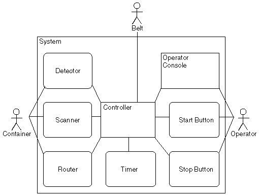
|
System scope diagram
The System Scope Diagram can be used early in the problem analysis to help isolate the boundary of the analysis activity. The System Scope Diagram provides a simple graphical checklist of all of the external and interface boundaries in the solution. It is an easy way to make sure that the complete problem is being addressed.
Tool Support
At the moment there are almost no tools available which support Real Time extensions to UML. Nevertheless, whenever choosing a tool the following criteria should be used:
Functional Requirements
Usability
This criteria is mainly related with customisation and functionality's offered by the editor in terms of Graphic User Interface and printing.
Learnability
This criterion focuses the amount of time needed to acquire a sufficient expertise in using a tool. Facilities as On-line help and documentation can be viewed as aspects that can contribute to improve the learnability of a tool.
Edition
This criterion refers to items offered by the editor in terms of model edition. The definition and properties that can be set in each one of the elements of a model, e.g. classes, attributes, methods, relationships, qualifiers. Other edition requirements are basic interaction techniques (e.g. selection, drawing, reshaping), the facility to include text and graphics into the diagram model and other features related to different target platform modelling support.
Modularity
This criterion refers to the ability offered by the editor to reuse an entire, or pieces, of diagram models in different projects. Distributed approaches to diagram sharing (e.g. share a diagram between two or more users with one seeing changes made by the other) are also covered by this.
Openness Requirements
Integration
This criterion refers to the easiness of integration of the editor with other tools in the SCE environment.
Repository Access
This criterion refers to the easiness of access the information of diagrams in each tool.
Platform Support
This criterion refers to the operating platforms each tool supports.
Performance Requirements
Code Generation
This criterion refers to the quality of code generated by the tool. The possibility of using directly the generated code for the target language is a good contribution for the integration of the tool in the SCE.
Reverse Engineering
This criterion refers to the facility of reverse engineering provided by each tool, its qualities and limitations.
Links
The site www.jeckle.de/umltools.htm gives an overview of existing UML tools with the different packages they support. The evaluation criteria are based on functional, performance and openness requirements, brought in by the service creation development process for distributed systems.
Other links can be found at:
- Rational Rose: (http://www.rational.com/rose)
- ObjecTime (http://www.objectime.com)
- Together/J (http://www.togetherj.com/tj-main.htm)
- Cool:Jex (http://www.cool.sterling.com)
- Software through pictures (http://www.aonix.com)
- Paradigm Plus (http://www.platinum.com)
- ObjectiF (http://www.microtool.de)
Conclusion
Several aspects of real-time systems development require additional support from UML. By adding complementary views and notation, UML can be naturally extended to better define and design real-time systems. By applying these combined modeling techniques, the resulting system definition is more complete, the solution design is more accurate, and the system development (programming) is more straightforward. A correct solution is more likely if the software, hardware, and system engineers have a common and agreed upon view of the functionality and implementation of the application. The extensions presented here provide this common foundation.
Discussion
- Most of the extensions to UML for real time systems are no more than non-formal comments.
- There are no provisions to write down resource constraints. For example to specify that the code has to be smaller than 64K, or to force a component to be smaller than 64K.
- There is no support for hardware/software co-design. Whenever the hardware changes, often the design will undergo substantial changes. Especially if the design is written down to fit exactly the hardware.
- Code generation in UML tools is generally not full code generation, which is a serious drawback.
- Little or no current research is done how to propagate timing constraints in different phases.
ROOM
Room is an object-oriented software development methodology created by telecommunications software developers. This practical method is in use by leading telecommunications companies. It complements the object paradigm with graphical high-level concepts chosen to explicitly address the challenging needs of real-time telecom software development. [6]
Development is conducted as an iterative progression of component-based models. At each stage developers concurrently integrate and verify models to ensure compliance to previously validated specifications. The system is thus thoroughly tested at each stage of the development. Throughout the process, iteration occurs as the specification and design are refined as the result of feedback through model execution. An implementation is generated directly from the detailed design model. A major advantage of this approach is incremental delivery of functionality and reduced time-to-market.
Methodology
ROOM Structural Concepts
An actor is the primary structural concept. Actors are concurrent objects (i.e., they exist and can be execute independent of other actors in the same environment) and their implementations are totally encapsulated. Actors can be either fixed (a one-to-one relationship between objects in the design versus objects running in the system) or dynamic (objects are created and destroyed as required at run-time, in placeholders specified in the design). The only way actors can communicate is by Messages sent and received through Ports, which are openings in the encapsulation shell. A message is a pair consisting of a Signal name and a message body, which is an instance of a data class.
Ports are specialized interfaces for an actor. Protocols are a set of message types, and their sequence, allowed to flow in or out through the port. Ports are instances of a protocol class, allowing interface reuse and refinements of protocols through inheritance.
Synchronous or asynchronous messages sent by the actor to ports are connected to other actor's ports through message channels called bindings. Bindings explicitly show the communications paths between them. Note that because actors sends and receives messages through ports rather than directly to and from other actors, the actor is essentially a black box independent of its environment. Thus actors are inherently distributable and easily reusable in various design situations.
The actor is also the concept that allows the creation of arbitrary complex objects through the mechanism of aggregation. ROOM allows an arbitrary number of levels in the structure hierarchy. As described above, structure provides an essential capability to express concurrent object containment and communication.
ROOM Behavioral Concepts
Besides structure, actors have an optional behavior, which determines how the actor reacts to messages arriving on its ports (events). ROOM uses graphical hierarchical extended finite state machines, a variant of Harel's statecharts [2] modified to support object-orientation and to facilitate efficient real-time implementations.
The lower level of detail that deals with event handling (typically the actions taken on the transitions between states, or on the entry/exit of states) is not captured graphically. This detail needs the expressive power of a traditional textual programming language such as C or C++.
Inheritance
Actors are organized in an inheritance hierarchy. A subclass of an actor class can refine the structure buy adding or modifying ports, or refine the actor behavior by adding or modifying states, transitions, or code.
Inheritance for complex objects is a major productivity aid, as whole architectural templates can be refined and reused among different systems. Besides applying inheritance to actors (and thus their structure and behavior), it is possible to apply inheritance to protocol and data classes.
ROOM Development Process
Having outlined some basic ROOM concepts, we will now describe the fundamentals of the development process.
Continuity of concepts across development activities and the use of executable models are the main cornerstones of the ROOM development process. A ROOM model is a set of coherent views (structure, behavior, protocols and data) which can be compiled and executed on host and target platforms. What guarantees the coherency of these views is their formal definition, which allows tools to generate executable code for:
-
Simulators, running on development platforms
-
Real-time operating systems on target hardware platforms. For example, the ObjecTime toolset provides a set of run-time libraries that provides a low-over-head execution of concurrent objects within the task concurrency model of a target real-time operating system.
ROOM allows for the creation of models during all activities of development including requirements specification, analysis, architecture, design, and implementation. All models can be executed; thus enabling a continuous process of concurrent integration and validation as the system is developed. Models can be taken down very early to implementation-level detail, and are often driven by subsets (increments) of functionality. Increments are often chosen to reduce project risk, by addressing high risk aspects of the product (e.g., performance, key features) as early as possible. This incremental approach has the added benefit of enabling incremental delivery of product capability.
Requirements drive all models. In ROOM, functional requirements are captured as scenarios. A scenario describes, by an action or sequence of actions, how something is used or what it must do. Model execution validates scenario consistency and completeness. Scenarios for event-driven systems are usually a sequence of actions to complete some higher level capability. These scenarios can be transformed into a series of messages exchanged between objects in a model. For example, the steps involved in initializing an ATM network element can be expressed as a scenario. Message sequence charts capture these time-sequenced pair-wise exchanges of messages.
Initially, requirements may exist as text or message sequence charts. Early models may be iteratively developed that capture these requirements using ROOM concepts (i.e., communicating actors). As modeling progresses new requirements are discovered and new objects and behavior are invented and added to the model. Besides the creation of new (reusable) model components, developers can check component databases for existing components that can be used or modified. A concurrent validation activity relying on model execution often reveals specification errors (e.g., robustness of protocols, unspecified behavior under failure conditions).
Building a test environment for the system takes place simultaneously with model development. Such environments may help validate requirements, architectures, and designs/implementations. The ROOM concepts are well suited for developing test suites expressed in the same formalism as the system under test. The testing environment consists of those actors in the model that simulate the environment the system is to interact with, performing specific test cases (e.g., initiating message sequences). The test models and associated message sequence charts are development artifacts that should be maintained.
As modeling of the architecture and high-level design progresses, requirements for new components are identified and the necessary objects and behaviors developed. This is especially common for layered, hierarchical designs where the design of a component often becomes the primary specification for the components it contains. Sometimes new system-level requirements are discovered, requiring iteration of the model. Executable models form a basis for trying out design alternatives much easier than traditional techniques involving programming only. Various design iterations result in increments of new functionality.
Design often requires knowledge about the target execution platform and incorporates design decisions that improve the overall performance of the system by using the target hardware platform in an efficient way. For instance, the ATM network element design takes advantage that some actors will run in the same task of the target real-time operating system (it passes data by reference rather than by value).
Real-time systems often have critical functions, such as interrupt service routines or low-level device drivers that may need hand-optimization. For example, the ObjecTime runtime libraries allow for interactions with other tasks in the native real-time operating system and with interrupt handlers. Also, the user-written code on the transitions between states can be optimized using traditional methods and it can reference optimized external libraries.
Embedded Systems
Real Time Extensions
There are almost no provisions to describe the real-time behavior of actors in a ROOM model.
Message Handling
Message handling is very clear defined in ROOM and is perfect suitable for embedded systems.
Hardware Abstraction
Hardware abstraction can be done within ROOM, but there is no explicit support to adapt to evolving hardware.
Resource Constraints
Resource constraints can't be expressed in ROOM.
Toolsupport
Tools that support the ROOM method, such as ObjecTime, generate code for the graphically specified structure and behavior. This automatically created code is combined with the state transition code written by the developer, into a complete source program compiled for simulation on the workstation or execution on hardware targets.
Conclusion
The ROOM concepts constitute a high-level domain-specific visual development language. The same concepts are used in all phases of development to eliminate error-prone and non-productive discontinuities. ROOM takes maximum advantage of modern tool technology to achieve value through executable models and automatic code generation. Development is conducted as an iterative progression of models composed of components. At each stage developers employ concurrent integration and verification techniques. The result is a system that has been thoroughly tested at each stage in its development, and a trusted high-performance implementation generated directly from its own detailed design model.
Discussion
-
In ROOM the gap between the source and the design is well-defined and allows reverse engineering and straight forward execution.
-
A drawback of the ROOM methodology is that resource constraints can't be specified.
-
Real-time constraints can't be expressed, or there is no explicit support for it.
-
ROOM is unable to adapt to new hardware settings. The hierarchical structure cannot handle too much changes at the lower hardware levels.
-
ROOM is maybe a bit too domain specific. ROOM is developed by telecommunication software developers and as such is not immediately useful in small scaled embedded systems where connectors, capsules and ports are not needed or natural.
Octopus
Octopus is an object-oriented software development method specialised for embedded real-time systems that covers the entire life cycle of software development. [7, 8]. It is based on OMT and Fusion, but also embodies common practice found in real-time systems. It applies object-oriented techniques, while matching the specific needs of real-time systems, such as concurrency, synchronization, communication, handling of interrupts, hardware interfaces and end-to-end response times.
Recently, Octopus was updated to use UML notation, with extensions to accommodate for the special constraints of embedded real-time systems.
Methodology
|
OCTOPUS structures the development process into a system requirements phase and a system architecture phase in which a large system is decomposed into subsystems and alternatives of system increments are determined, followed by parallel development (analysis, design and implementation) of the subsystems (or parts of subsystems) which belong to the selected system increment. This is repeated for the other increments.
Requirements Specification Process
In this phase the relevant requirements for the software are recaptured. The structure of the system’s environment is specified by a context diagram. The functional and dynamic behavior of the system are specified by a use case diagram and use case sheets. These may be complemented by interaction scenarios between the system and its environment. Octopus extends the context diagram, as known from SA/SD, to express important relationships between the actors themselves and uses for that the class diagram notation. Relationships are often named after the use cases. The system in this phase is a black box.
System Architecture Phase
The system architecture describes the structure of the system by a subsystems diagram. The major interfaces between the subsystems are indicated on it as associations. The functional model is a set of responsibility sheets and the dynamic model comprises use case - subsystem association diagrams. A subsystem in this phase is a black box.
Subsystems
Subsystem Analysis
The subsystem analysis is done for every subsystem. The structural model is a class diagram of the subsystem supplemented by a class description table. The functional model is a set of operation sheets. The dynamic model contains an event list, an event groups diagram, event sheets, statecharts, a significance table and possibly a list of compound events. Both the functional and dynamic models treat the subsystem as a black box but make references to the classes in the structural model.
Subsystem Design Phase
In design the dynamic model is represented by a set of object interaction threads, further developed to qualified event threads, and then object groups are derived. From these the outlines for processes, classes and interprocess messages are systematically built. These outlines form the structural model. The functional model is the outlines of the member functions which merge with the class outlines in the structural model.
Performance Analysis
Performance analysis can be carried out once all the event threads are designed and the processes are determined. For every event in every subsystem, the processes involved, their priorities and estimated execution times are derived. For the whole system, the process priorities in the included subsystems are harmonized with each other. Worst case event sequences are identified and performance charts are developed. The design solutions may need to be fine-tuned to achieve the desired behavior.
Embedded Systems
Real Time Extentions
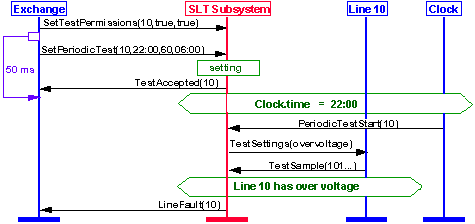
|
Octopus provides substantial support for describing and analysing real-time behavior. In the subsystem analysis phase, real-time behavior is described through the dynamic model, using an event-based approach. For this purpose Octopus uses diagrams such as state charts and sequence diagrams, with extra annotations for describing real-time behavior where needed.
|
Real-time behavior is further examined in the performance analysis phase. Octopus describes how to determine process priorities (based on the event significance as determined in the subsystem analysis phase) and estimate execution time. This data is then used to analyse worst case performance and check compliance with the requirements.
Hardware Abstraction
Octopus explicitly supports hardware abstraction in the form of a platform independent application layer (the hardware wrapper) which hides operating system and hardware from the application, thus improving portability and promoting reuse.
Resource Constraints
There is no explicit support for modeling resource constraints in Octopus.
Toolsupport
Octopus is not tool dependent. The recent adoption of UML as notation language allows developers to apply the method using tools such as ParadigmPlus and Rational Rose.
Discussion
- Octopus addresses all major phases of software development, from requirements capturing to implementation, and focuses on a – very detailed – description of the development process itself.
- Little or no attention is paid to code generation – this responsibility is left to the case tool being used.
- Resource constraints cannot be specified in Octopus.
- Provides good support for describing and analyzing real-time behavior.
Bibliography
| 1. | Object-Oriented Analysis and Design with Applications Grady Booch 2nd edition Redwood City, CA: Benjamin/Cummings, 1994 |
| 2. | Statecharts: A visual formalism for complex systems David Harel Science of Computer Programming Vol 8,1987 |
| 3. | UML for Real-Time Overview Andrew Lyons April 1998 http://www.objectime.com/otl/technical/content.html |
| 4. | Real-Time Extensions to UML: Timing, concurrency, and hardware interfaces J. McLaughlin, Alan Moore Dr. Dobb's Journal; December 1998 http://www.ddj.com/articles/1998/9812/9812g/9812g.htm |
| 5. | Real-Time UML: Developing Efficient Objects for Embedded Systems Bruce Powel Douglass Addison Wesley ISBN: 0-201-32579-9 |
| 6. | Using the ROOM methodology for an ATM Protocol Stack Garth Gullekson Objecttime Limited |
| 7. | Release of Octopus/UML Endre Domiczi, Rallis Farfarakis, Jürgen Ziegler Nokia Research Center |
| 8. | Octopus Method and Internet Course / http://www-nrc.nokia.com/octopus/ |
| http://werner.yellowcouch.org/ werner@yellowcouch.org |  |