| Home | Papers | Reports | Projects | Code Fragments | Dissertations | Presentations | Posters | Proposals | Lectures given | Course notes |
|
|
Enhancing StereoWerner Van Belle1 - werner@yellowcouch.org, werner.van.belle@gmail.com Abstract : This short note covers how to use a hilbert transform to decorrelate a mono-signal, how to use a Linkwitz-Riley crossover to improve stereoperception and how to normalize the head related system transfer function developed at MIT in the 90ies.
Keywords:
stereo widening |
Table Of Contents
Sometimes people want to widen the stereo experience of audio tracks that were originally mono. Below we address a number of techniques that can be used to do this. Before delving into the details it is worth noting some considerations that affect 'stereo enhancers' as we will call them
- How does the stereo enhancer behave on a mono signal ? If the original signal is mono, there is no stereo-information present. So we need to make up something that was not in the original sound. We want that it sounds broader, wider, as if perceived in a room with our two ears.
- How does the stereo enhancer behave on stereo signals. If the signal is originally stereo, will it retain the same stereo quality and widen the mono part or will it decrease the quality of the original stereo image ?
- Can we listen to the stereo enhanced signal in mono ? Often when listening to a stereo-enhancer in mono we find that flanging effects might appear.
Easy strategies
Strategy 1: difference between left and right
|
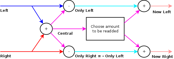
The first strategy is the calculation of the stereo signal against the mono signal. We first calculate first the center signal center=(left+right)/2 and then can calculate the left or right channel difference towards the center: new_left=left-center. The center signal can then again be added to new_left or new_right, depending on how much 'stereo' we exactly want.
In practice there are three problems with this strategy.
- It adds no value to mono signals. They will remain mono. And everything that was in the center will stay there
- It works on a sample by sample basis and is thus very sensitive to phase differences. A slight shift in either signal can result in completely different output results.
- If we would choose 'full stereo', and remove the center channel completely we would find that the left and right channel are exactly opposite (new_left=-new_right), but still have the same content and do not add anything to the stereo experience. This strategy will make a stereo image, present in the input signal, worse.
Below some demonstrations of this strategy with a middle gain of 0.25.
In summary, a naive idea that will not work as expected.
Strategy 2: Cross Channel Delay
|
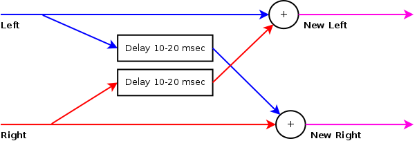
Another strategy one often reads is to use a delay on the extracted left and right channel and feed it back to the other channel. This would lead to the perception that the material that was originally left will bounce against the wall and arrive somewhat later in the right ear. In this case a delay of 1 millisecond would reflect a distance difference of about 30cm. A delay of 25 milliseconds will be perceived as bouncing against a wall that is 7.5 meters away.
 Frequency response when mixing a
delayed and original signal
Frequency response when mixing a
delayed and original signal
|
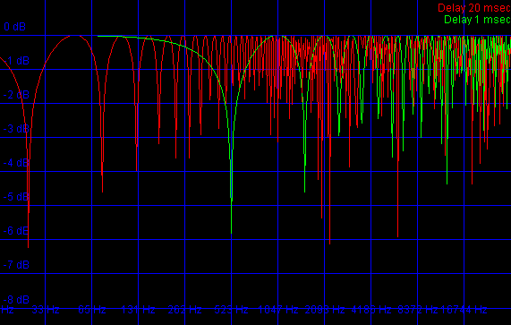
The main problem with this strategy is that it creates a comb filter [1]. This happens because the shared part of the left and right channel will be added (but with a delay) back to the original signal. That results in a audible filter. They are often perceived as flanging effects. The above picture shows the frequency response if we use a delay line of 1 millisecond or 20 milliseconds.
The other problem with this strategy is that a signal is bounced to another channel. Imagine a signal where the left channel has a trumpet, the right doesn't. After 'widening' the stereo, the left and right channel will suddenly sound similar, and both have the trumpet playing.
Strategy 3: Delay only 1 channel
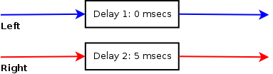
Instead of bouncing the signal to the other channel, we could also consider delaying one channel only.
 Delaying one channel more than the other.
|
Observations:
- Mono signals sounds wider.
- Stereo signals remain as they were. The stereo is not 'widened'
- Since the left channel is not mixed with itself f(only delayed), we do not create a Comb filter, hence we will not have flanging effects on individual channels.
- We do however still create a Comb filter if we were to listen to the signal in mono. In that case a mono signal will be delayed differently across the two channels. As soon as the two channels are merged back we will again find our not-so-good-old-friend Comb back.
- Low frequencies are also delayed, which leads to lesser accentuated low frequencies. In general, bassdrums and bass lines start to sound 'not quite there'.
- The maximum delay between the two channels is about 20milliseconds. Anything that falls below that is considered 'one event'. Larger times lead to new distinct events, which is not what is wanted.
Strategy 4: Decorrelate using a variable delay line
Another technique that might be attempted is to reduce the correlation between the left and right channel. Here we tune the delay of one channel such that the 'correlation' between the left and right channel is minimal.
|
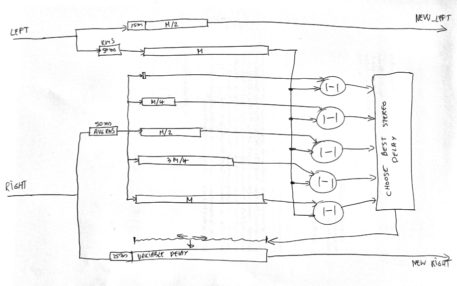
To implement this strategy one can work with 5 parallel delay lines (with delays ranging from 0 to 50 milliseconds). Based on the output of each of those delay lines we choose which delay is preferred to achieve the best stereo image. How 'stereo' the signal is, can be easily determined by calculating the absolute distance between the left delayed signal and the right delayed signal. The delay line that produces the highest number is the one with the best stereo image.
The output of the delay line selector can then alter a secondary delay that routes the original sound signal through. The change to this variable delay line cannot be too large. The problem here is that, When we lengthen the delay line, the sound will come out somewhat slower. And this until we achieved the the required delay length. Every time we shorten the delay the sound will play slightly faster. The maximum pitch change we might notice is thus given by maximum/minimum speed. This can then be converted to a pitch change. At a delay-change-speed of 1%, we will have a maximum pitch change of 2% (1.01/0.99=1.0202), or 35 cents. Essentially, we should only change the delay line at a maximum speed of 0.01 sample per output sample.
A second aspect to the variable delay line strategy is that we will look at the energy content of the signal, as opposed to the individual samples. In front of all the delay lines we place an envelope measurement in windowsizes of around 50 milliseconds. The latency of the envelope window should also be added to the variable delay and static delay line of the left and right channel.
A last remark is that we should limit the maximum position difference between the left and right channel to 50 milliseconds. That leads to a natural repositioning of high frequencies, while the lower frequencies (which typically have a less accurate time position) will not be affected that hard.
- This strategy does not work when we listen to the signal in mono. It will generate unpredictable flanging effects.
- Its ability to stay decorrelated is largely dependent on the speed by which the delay line can be modified. That means that the 'decorrelation' is not as large as we might expect
- Also the low frequencies are decorrelated, resulting in muddy bassdrums/bass sections.
- It is a complex strategy. Simply delaying one channel will produce an equally as good effect.
Complexer strategies
Strategy 5: Inter-delay on high frequencies
The biggest problem of strategy 3 was that low frequencies were affected negatively. To improve upon that, we will need the ability to split the spectrum into lower frequencies and higher frequencies. That makes it possible to delay the hi-left and hi-right frequencies differently while keeping the lo-left and lo-right frequencies aligned in the middle of the two hi-delays.
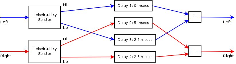 A stereo enhancer using a
Linkwitz-Riley splitter to divide the incoming spectra. The high
frequencies are delayed differently. The lowfrequencies are not
delayed.
A stereo enhancer using a
Linkwitz-Riley splitter to divide the incoming spectra. The high
frequencies are delayed differently. The lowfrequencies are not
delayed.
|
A good method to split the spectrum in two is using Linkwitz-Riley crossover [2, 3, 4, 5]. Such is made by place two Butterworths of even order in series. The resulting high pass and lowpass sections are complementary. The sum of all the energy across the spectrum will be 0 dB, it does however allow us to delay the high frequencies differently from the low frequencies. Nevertheless, because a Linkwitz-Riley crossover is made of a series of infinite impulse response filters, it is necessary to briefly have a look at the group delay as to understand when and how flanging effects might occur.
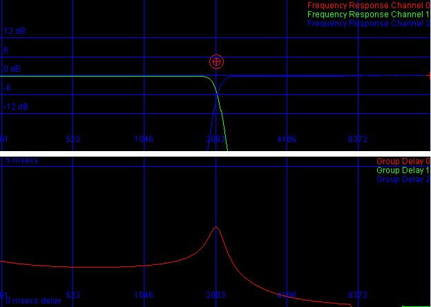 A 14th order splitting of
the frequency band. The top panel show the dB gain for the two
extraced channels. The bottom panel shows the groupdelay in
milliseconds. As can be seen even at this extraordinaly strong
splitting, the group delay remains below 2.5 milliseconds.
A 14th order splitting of
the frequency band. The top panel show the dB gain for the two
extraced channels. The bottom panel shows the groupdelay in
milliseconds. As can be seen even at this extraordinaly strong
splitting, the group delay remains below 2.5 milliseconds.
|
When do flanging effects occur ?
- Low frequencies: are not subject to individually different delays. That means that there will be no flanging effects, not even when we listen to the stereo enhanced signal in mono.
- The transition band: For instance at 2093 Hz in the above picture we will have a -6dB signal from the lower section and a -6Db signal from the hi section. The hi frequencies will be delayed, which will results in a flanging effect happening in the transition band. This is luckily limited to the transition band.
- High frequencies: (above the transition band) will be delayed at different rates. The individual channels will create a Comb Filter. However, as soon as the two differently delayed channels are brought back together (when listening to the signal in mono), we will observe flanging effects.
Because we potentially (when listening to the stereo enhanced signal in mono), have flanging effects starting at the transition band, we are interested to understand what type of delays causes what effect above the transition band.
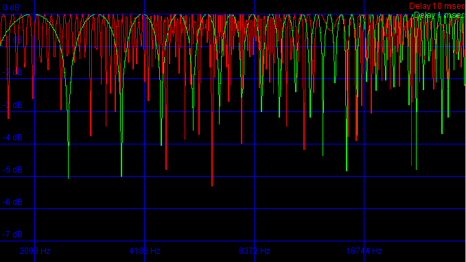 Flanging effects above a
reasonable transitionband
Flanging effects above a
reasonable transitionband
|
As can be seen in the above image, the flanging effects are 'strongest' when the delay is small. With strongest we mean that the lobes are relatively wide, which is bad because a specific sound might fall completely within a valley. This cannot happen with the larger delay of 10 milliseconds. The lobes are very small, and it will of course be audible, but the effect will be more or less the same across the entire high section.
Below some audio demos using a LR crossover consisting of two 4th order Butterworths. A crossover frequency at octave 6 and a high inter-delay of 20 and 2 milliseconds. Below we find that this strategy works best on drums (E.g Africa, beware the difference in loudness which was not yet compensated for).
Summarized:
- The order of the LR crossover > 4
- Relative delay times should be either 0 or > 5 milliseconds
- Delay times should be < 30 milliseconds
- Frequency>2500 Hz
- It will make mono signals sound stereo
- Stereo signals will not be affected in a negative manner
- Stereo widening does not take place
Strategy 6: Decorrelation using a 90 degree phase shift
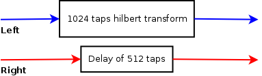 A Hilbert transform setup to bring
a mono channel 90 degrees out of phase.
A Hilbert transform setup to bring
a mono channel 90 degrees out of phase.
|
Another strategy to ensure that a mono signal is 'maximally' decorrelated, is to phase shift all frequencies of one channel with 90 degrees. To implement this we can fall back to a Hilbert transformer [6], which does exactly this.
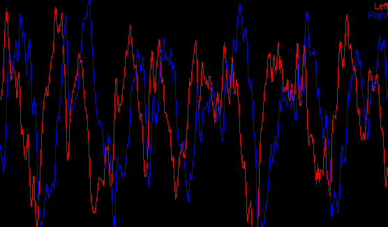 The result of a hilbert
transform on a mono signal.
The result of a hilbert
transform on a mono signal.
|
The above picture shows the result of a Hilbert transform on a mono signal. The resulting left and right signal are 90 degrees out of phase. An interesting observation can be made here, namely that the lower frequencies are delayed longer than the high frequencies. This is something unachievable with ordinary delay lines.
Some audio demos, when using a Hilbert transformer of 2048 samples.
- The advantage of using a Hilbert transform is that the mono signal sounds more or less the same as the stereo signal
- A disadvantage is that the effect is fairly subtle and does not give the feeling that any 'stereo' was added to the signal.
- Another disadvantage is that the operation is relatively expensive. Even a moderately effective Hilbert transform uses 128 operations per sample.
- An advantage then again is that it is very likely so that smaller Hilbert transformers will preserve the low frequency content.
Strategy 7: Head related transfer functions
Another possibility that one can consider is the use of the KEMAR head model. In 1994 an extensive set of head related system transfer functions was generated at MIT [7]. This was done by using a head dummy (called a KEMAR) which got two microphones inserted in his ears. Then an impulse was generated and at various azimuths and elevation angles the impulse response of the head was measured.
The KEMAR data was used by the original authors to create a 3D perception field, but did not live up to my expectations. The main reason being that the transfer functions were literally used as measured,m which is unwanted. After all, we don't want to modify the sound according to an extra ear channel. Instead, it is more interesting to understand how the sound modifies when listened to at different angles. That means that we want to normalize the dataset toward a standard position. Typically this is chosen such that the sound source is in front of the listener.
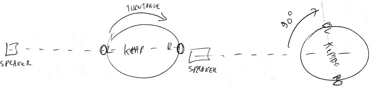 Kemar setup. The angles in the
dataset are given as the rotation of the turntable. 0 degree is a left
ear that points directly to the speaker. The 90 degree angle is a
rotation of 90 degress clockwise of the head, which is thus a -90
degree angle of the soundsource. At turntableangle -90 degree our head
is staring directly into the speaker
Kemar setup. The angles in the
dataset are given as the rotation of the turntable. 0 degree is a left
ear that points directly to the speaker. The 90 degree angle is a
rotation of 90 degress clockwise of the head, which is thus a -90
degree angle of the soundsource. At turntableangle -90 degree our head
is staring directly into the speaker
|
We first normalized each spectrum such that the average energy received in the ear was 0 for all impulse responses. Once that was done we ensured that the filter modifications would be smooth when turning our hand. The function that describes the gain of a specific frequency under a certain angle of our head is denoted freqresp(angle). To have a smooth behavior we bandlimitted freqresp(angle) using a sinc interpolator.
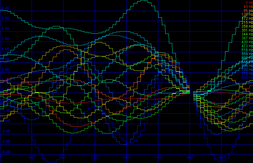 The perceived gain in our
left ear of a number of frequencybands as we turn our head.
The perceived gain in our
left ear of a number of frequencybands as we turn our head.
|
Below We demonstrate the effect such head transfer function has on our perception. In both cases a sound source rotates counterclockwise around our head, starting at the left ear. In the first the KEMAR data is used to filter the signal appropriately. In the second, only panning takes place.
Conclusion
Currently the cheapest and most efficient method to have a good stereo-enhancer, is using strategy 5: a Linkwitz-Riley crossover on both channels, which we then use to delay each of the high frequencies channels differently. The low frequencies are both delayed as the average delay of the two high frequency delays. A crossover should have appropriate order (4, 8). The delay between the high frequencies should be larger than 5 milliseconds, but lower than 30 milliseconds. This works especially well on drums.
Decorrelating the signal (by bringing them 90 degrees out of phase), does not perform as we would want. This is probably because we need to decorrelate the perceived information (energies) and not only the waves themselves. Decorrelation has the advantage that it will bring signals so out of sync that even a 180 degree phase shift of one of the two signals will not lead to a cancellation. This might sometimes be wanted. I also suspect that decorrelation will work well on signals that have a lot of echo on them.
The kemar related experiment is a small success. A pitty that it requires over 4000 operations per sample. Otherwise it would certainly be useful.
If computational power is not a limitation then a combination of the 3 mentioned techniques might constitute to a good stereo enhancer.
Bibliography
| 1. | Feedforward Comb Filters Julius Orion Smith III Physical Audio Signal Processing; W3K Publishing, 2010, ISBN 978-0-9745607-2-4 https://ccrma.stanford.edu/~jos/waveguide/Feedforward_Comb_Filters.html |
| 2. | Crossovers Siegfried Linkwitz Linkwitz Lab http://www.linkwitzlab.com/crossovers.htm |
| 3. | Linkwitz-Riley Crossovers: A Primer Dennis Bohn RaneNote 160, written October 2005 http://www.rane.com/note160.html |
| 4. | Active Crossover Networks for Non-coincident Drivers S. H. Linkwitz J. Audio Eng. Soc., vol. 24, pp. 2-8 (Jan/Feb 1976) |
| 5. | 12 dB/oct Linkwitz-Riley crossover S. H. Linkwitz Linkwitz Lab http://www.linkwitzlab.com/filters.htm#2 |
| 6. | Analytic Signals and Hilbert Transform Filters Julius Orion Smith III 2. Edition Mathematics of the Discrete Fourier Transform (DFT), with Audio Applications, W3K Publishing, 2007, ISBN 978-0-9745607-4-8 https://ccrma.stanford.edu/~jos/r320/Analytic_Signals_Hilbert_Transform.html |
| 7. | HRTF Measurements of a KEMAR Dummy-Head Microphone Bill Gardner, Keith Martin MIT Media Lab Perceptual Computing - Technical Report #280; May 1994 http://sound.media.mit.edu/resources/KEMAR.html |
| http://werner.yellowcouch.org/ werner@yellowcouch.org |  |